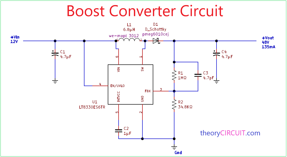
Boost Converter Circuit
This boost circuit is similar to Figures 7 and 8 except that R1 senses the inductor current for CMC. R1 and some internal comparators provide a current limit.. The MAX3864xA/B are nanoPower family of ultra-low 330nA quiescent current buck (step-down) DC-DC converters operating from 1.8V to 5.5V input voltage and supporting load currents of.

What every engineer should know about buckboost converters
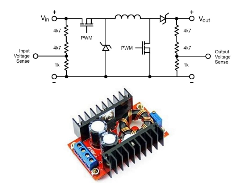
A DC to DC converter is basically a switch-mode power supply, designed to work either as a boost-converter to step-up a low voltage DC to a higher voltage DC, or as a buck-converter to step-down a higher voltage DC to a lower voltage DC.. The switched mode conversion ensures that the power transfer in the process involves minimum losses, and the efficiency rate is high, typically over 90%.
Schematic Of Buck Boost Converter Wiring Diagram
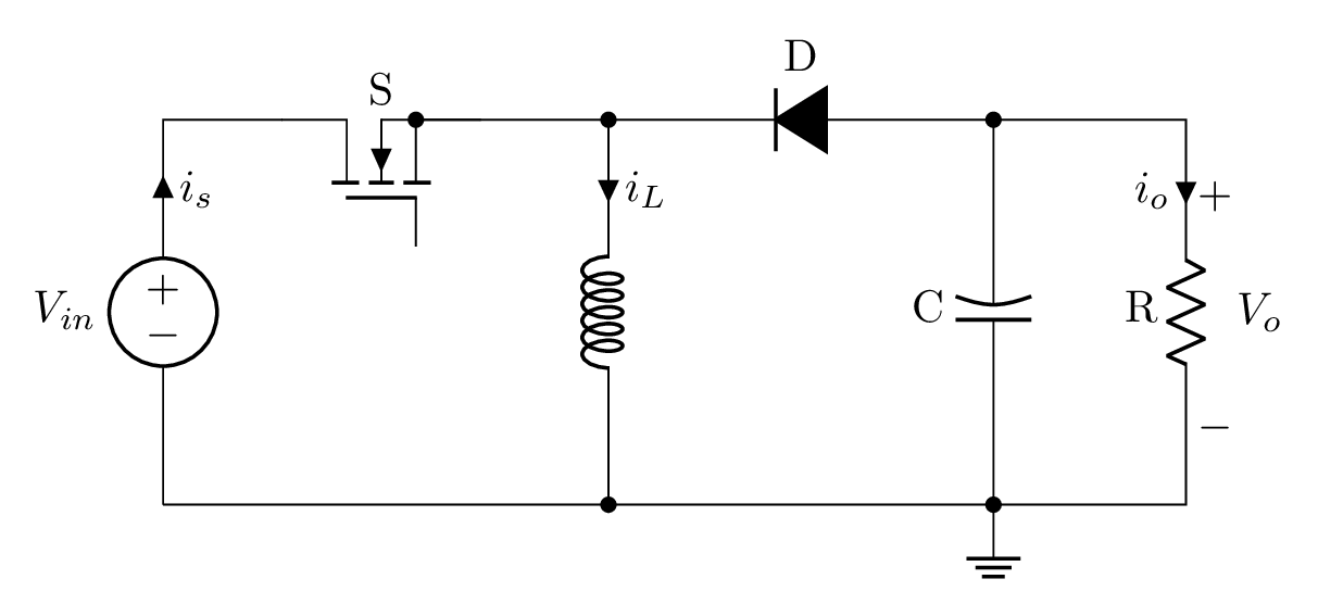
Boost Converter Design. In most any power supply schematic, the inputs are on the left and power flow is towards the load on the right. A boost is a little more than a backwards buck, though, so for a moment, let's imagine that V-in and V-out in this schematic were reversed. Now, it would change D1 and Q1. The boost is a buck going backwards.
boost converter circuit diagram with explanation Wiring Diagram and
A buck-boost converter is a combination of a buck converter and a boost converter i.e., it is a cascade combination of a buck converter circuit and a boost converter circuit. A buck-boost converter is a dc-to-dc converter by which we can obtain an output voltage greater or lesser than the input voltage. The polarity of the output voltage is.
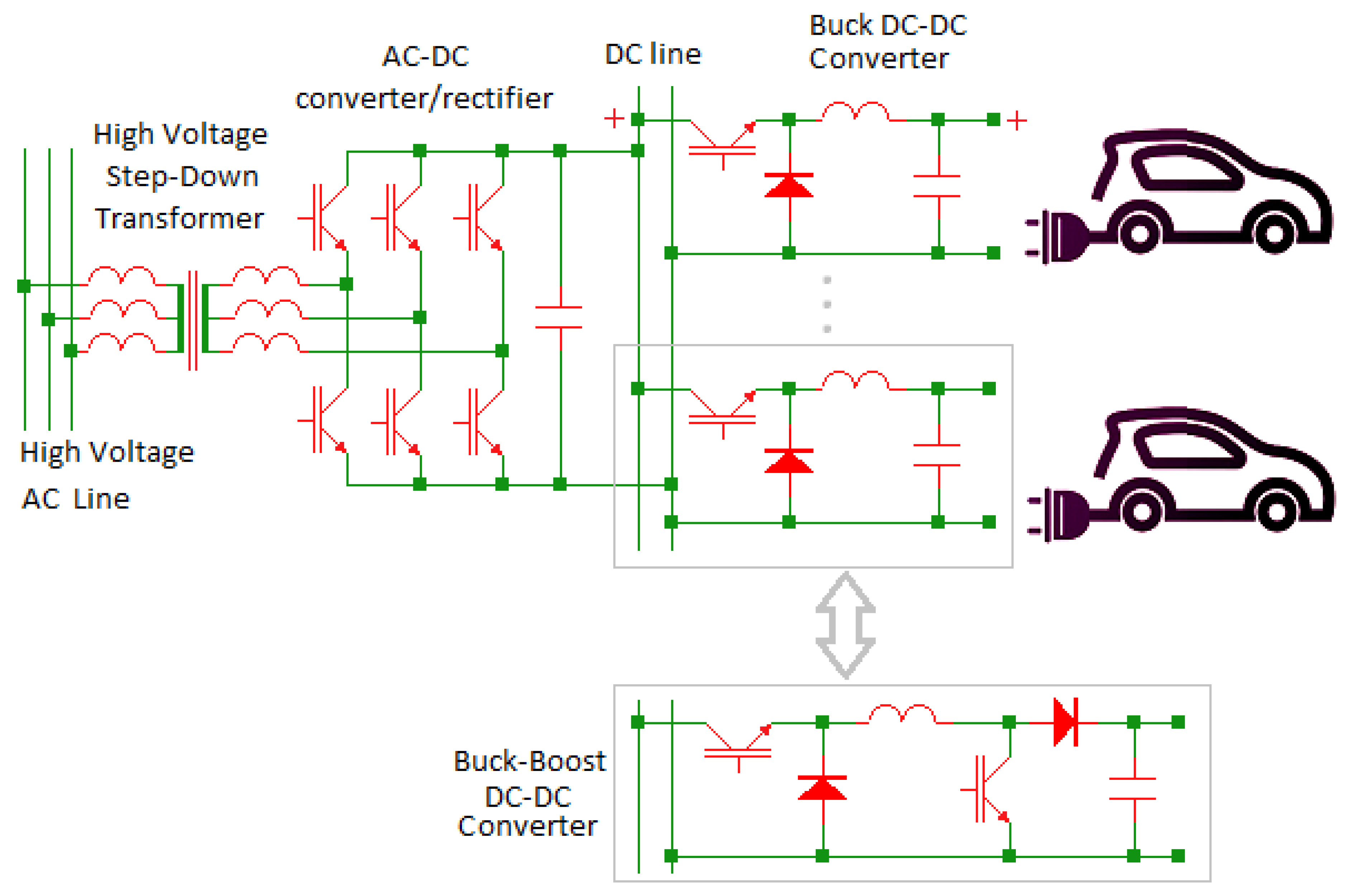
Electronics Free FullText A BuckBoost Transformerless DCDC
The specifications for the automotive USB PD buck-boost converter are provided in Table 2. This H-bridge buck-boost circuit provides the maximum value of 60 W output power for input voltages from 5 to 18 VDC and output voltages from 3.3 to 21 VDC. Table 2. USB PD buck-boost converter specifications.
DC to DC buckboost converter circuit homemade
A buck converter (buck converter) is a DC-to-DC power converter that lowers the voltage from the source to the load (in drawing a smaller average current).A boost converter or a DC boost chopper is another name for a DC boost converter. A buck-boost converter is a DC-DC converter with an output voltage that can be higher or lower than the input voltage. This article mainly introduces these.

(a) Buckboost DCDC converter, (b) Cuk DCDC converter, (c) SEPIC
Circuit topology and switching modes for conventional. Abdelsalam, A. K. & Williams, B. W. Continuous-input continuous-output current buck-boost DC/DC converters for renewable energy.

DCDC Boost converter tutorial Afrotechmods Fun with electronics!
There are other types of switched-mode dc-dc converters, such as the buck-boost converter, which is able to create a step-up or step-down dc voltage of opposite polarity (e.g., creating -2 V from a 1.5-V battery), and the noninverting fly-back converter, where a single circuit creates both a stepdown and a step-up dc voltage of the same.
BuckBoost Converter in CircuiTikZ TikZBlog
In Figure 1, the common components of the buck and boost circuits are combined. A control unit is added, which senses the level of input voltage and then selects the appropriate circuit action.
.png)
Analysis of Four DCDC Converters in Equilibrium Technical Articles
Buck-Boost (invert)—an output. The most commonly used DC/DC converter circuits will now be presented along with the basic principles of operation. 2.1 Buck Regulator The most commonly used switching converter is the Buck, which is used to down-convert a DC voltage to a lower DC voltage of the same polarity. This is essential in systems.
Designing An Arduino Based Buck Boost Converter With Feedback Arduino
Step-Up DC-to-DC Switching Converters Operate at 650 kHz/1300 kHz. The ADP1612 and ADP1613 step-up converters are capable of supplying over 150 mA at voltages as high as 20 V, while operating, respectively, with a single 1.8-V to 5.5-V and 2.5-V to 5.5-V supply.
DC to DC boost converter circuit homemade
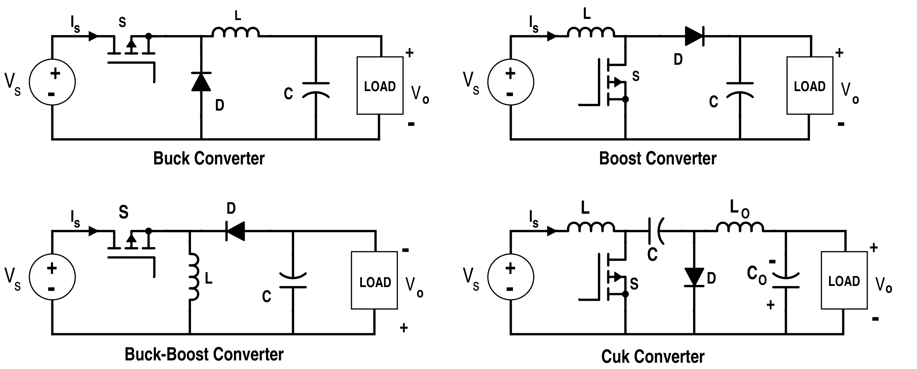
In other words, a non-isolated DC converter converts DC input directly into DC output. Examples of non-isolated DC-DC inverters are Buck, Boost, Buck-Boost, Cuk and SEPIC converter. In contrast, examples of isolated converters are Push-pull, Forward, Flyback, Half-Bridge and Full-Bridge converters.

Buy Buck Boost Converter, DC to DC Boost Converter, Automatic Wide
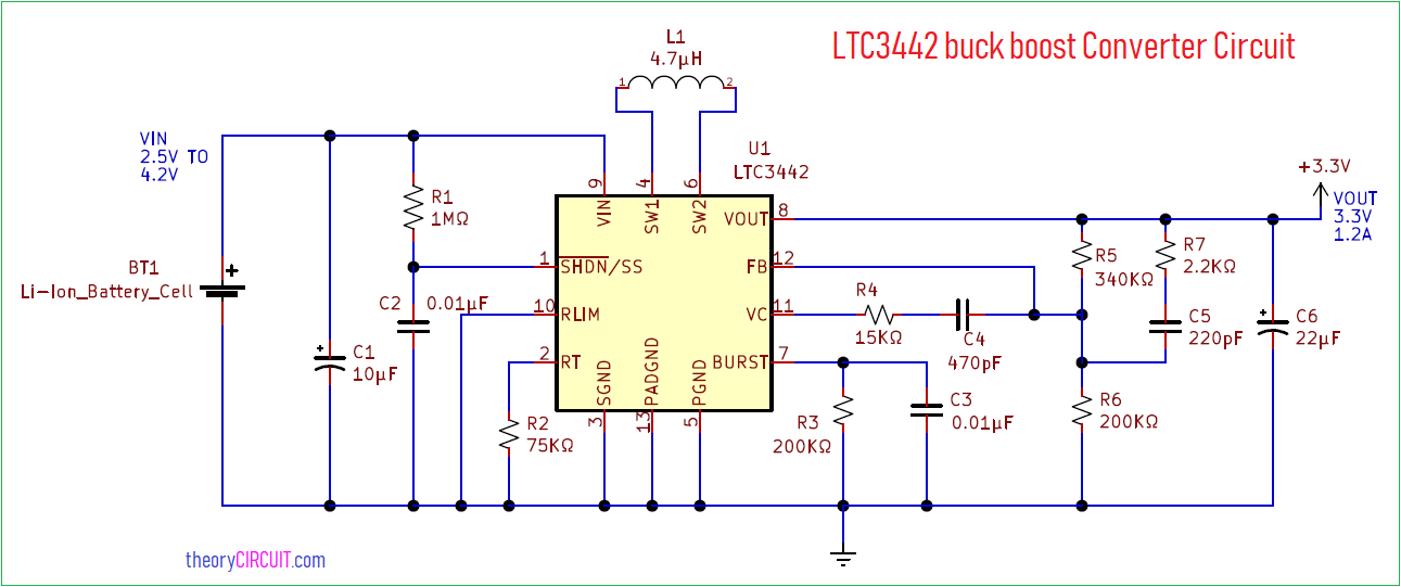
The buck-boost converter is a type of DC-to-DC converter (also knownas a chopper) that has an output voltage magnitude that is either greater than or less than the input voltage magnitude. It is used to "step up" the DC voltage, similar to a transformer for AC circuits. It is equivalent to a flyback converter using a single inductor.

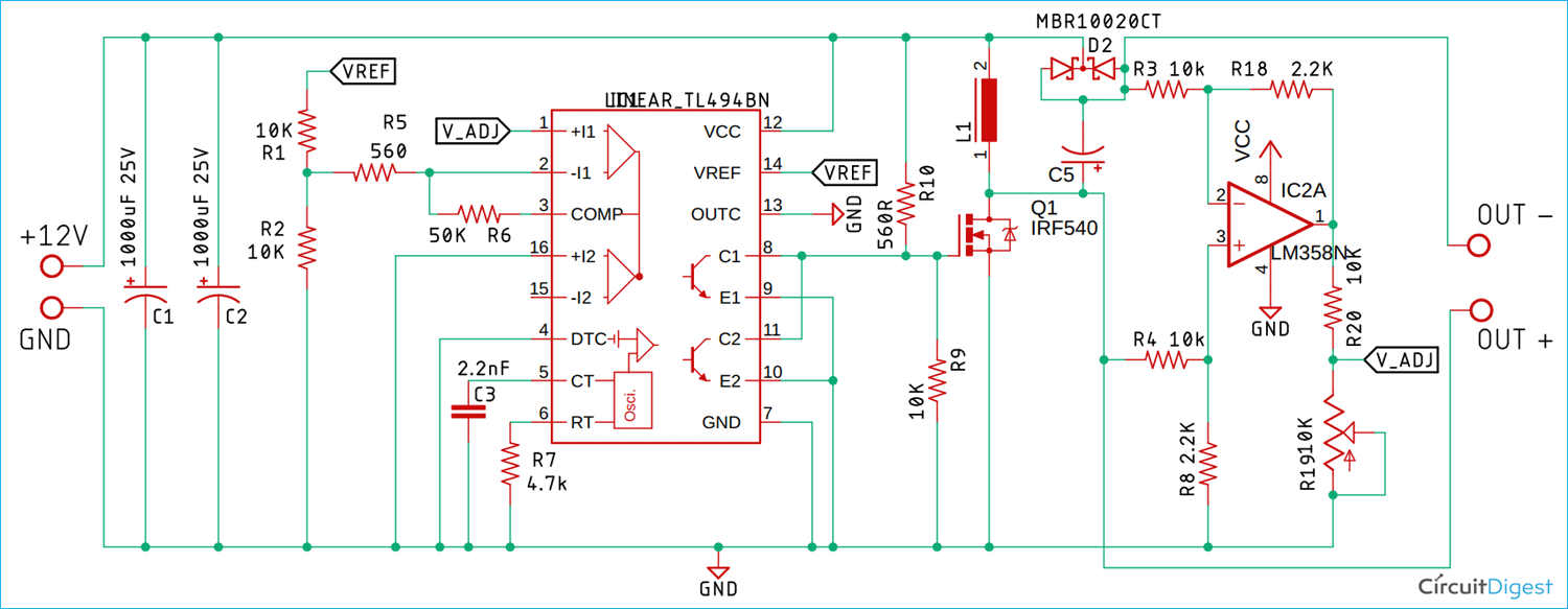
TL494 DCDC Buck Converter Adjustable Power Supply (1.530V, 5A) YouTube
28 Sep 2023. TA0363 3 V input, 70 V output, fully integrated hybrid charge pump 1.0. Often used in battery-operated equipment, buck-boost DC-DC converters require high-efficiency and ultra-low stand-by current as well as a small size to fit the requirements for portable and wearable devices for the Internet of Things (IoT).
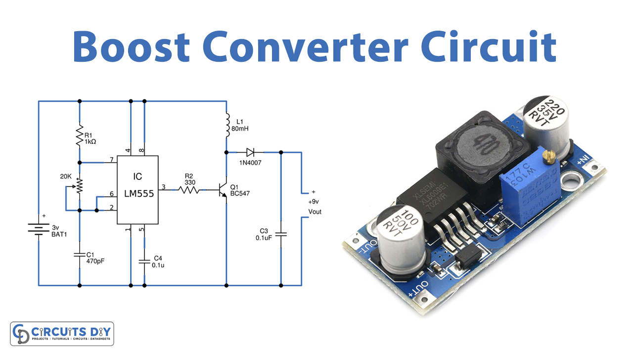
Boost Converter Circuit using 555 Timer IC
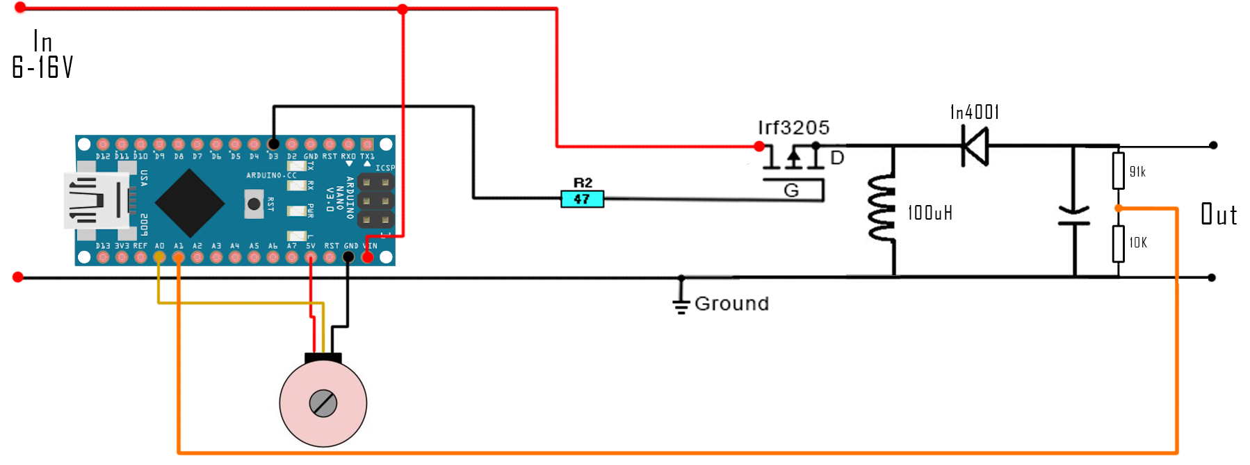
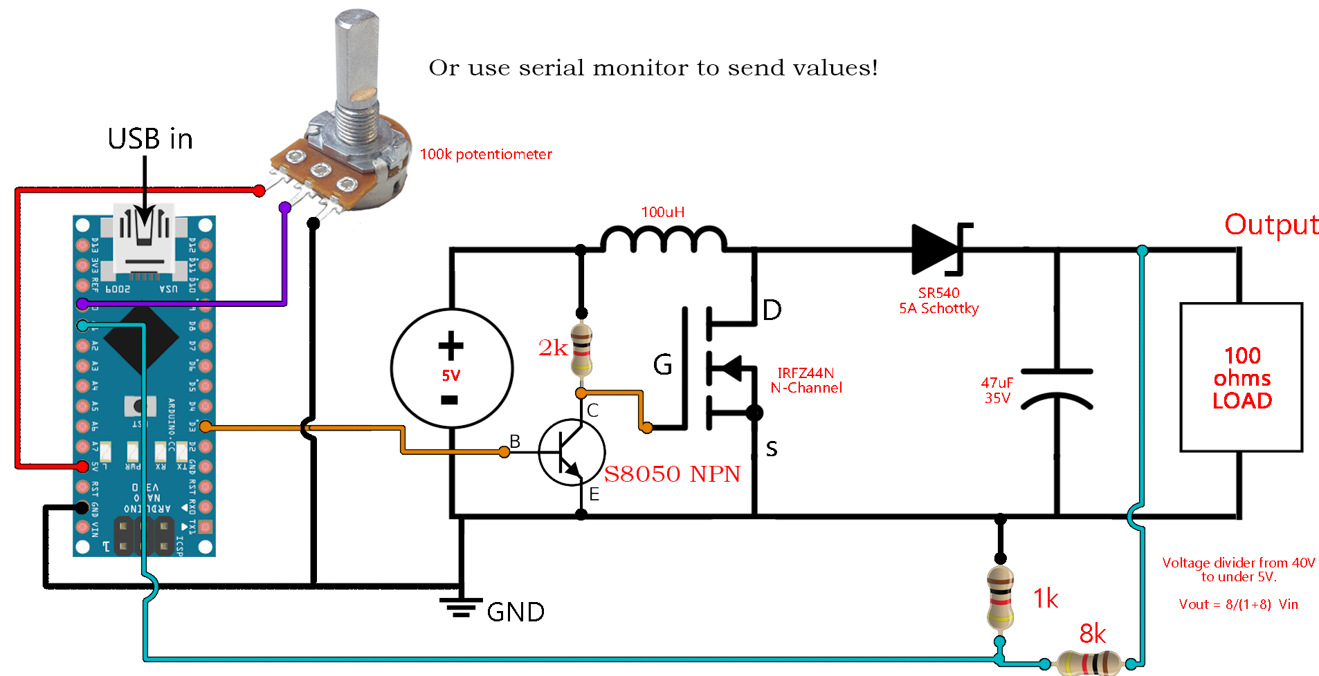
In this tutorial we will learn how to build and how a DC to DC buck-boost converter works. The circuit is very basic using just one diode, an inductor and a capacitor. The switch will be a MOSFET transistor and to create the PWM signal we will use a 555 timer in the PWM configuration, boost adjustable controller or one Arduino NANO.
Λείψανα στέγη Γλωσσάριο dc to dc boost converter circuit diagram
Step 1: Pinout Overview. Here You can see how the LM2596 DC to DC Converter Module looks like. You can notice that the LM2596 is an IC, and the module is a circuit build around the IC to make it work as an adjustable converter. Pinout for LM2596 module is very simple: IN+ Here we connect the red wire from the battery (or the power source), this.